- Composed of a photodiode (PD) and four transfer gates (G1–G4) for four signal-tap outputs and a draining gate (GD)
- The floating diffusions are connected to MOS capacitors (high full well capacity (FWC) of 100 ke-)
- Photo charges due to ambient light and reflected light out of measurement range are drained out by the draining gate GD
- The reset transistors (RT1–RT4) are turned on for resetting photo charge in each FD after reading out

- For Fig. 2(a), received light pulse (RL) is coming to the pixel at the timing in between G1 and G2 opened
- At the time when G3 and G4 are opened, ambient light only is received
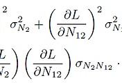
- The ToF or TD is calculated by the equation:

- Thus, the depth is expressed as:

Here, S1 and S2 are the signals stored in FD1 and FD2, respectively, and S4 stored in FD4 is for ambient light cancelling
- For Fig. 2(b), the light pulse is received at the timing between G2 and G3 opened
- TD is expressed as T0 + ΔTD and for the example in Fig. 2(b), TD is expressed as 2T0 + ΔTD
- The general formula for TD is as follows:

- Also, the general form of ΔTD is as follows:

- 1) In the SP-iToF operation using 4-tap pixels in the study, the ToF can be measured in the range of 3 TWs or 3T0
- 2) After this, the ToF can be measured finely by calculating ΔTD using (4) by the analog ratio between two signal
charges of the two taps (저희 simulation와 같이 각 tap의 transfer된 charge 비율로 계산하는 방법)

- To increase the number of TWs for extending measurable range of the hToF operation, a multiple subframe operation is introduced here
- One frame period, which determines the frequency of range mapping, is divided into three subframe periods
- Subframe1 is for the nearest depth range, Subframe2 is for the middle depth range, and Subframe3 is for the furthest depth range
- Using the range data of the three subframes, the measurable range of 9 TWs can be realized

- This operation has an advantage of extending the measurement range
- For example, if the reflected light from an object is received between G4 in Subframe1 and G1 in Subframe2, depth is calculated by using these two subframes

- Due to the nature of irradiance being inversely proportional to the square of distance, the following integration-time assignment technique can be used:
Closer position: Shorter integration time
Furhter position: Longer integration time


